SteFly Canopy Flasher
357,00 € – 599,00 €
incl. VAT plus shipping
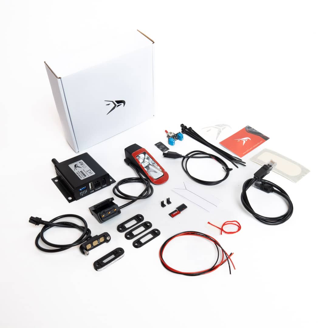
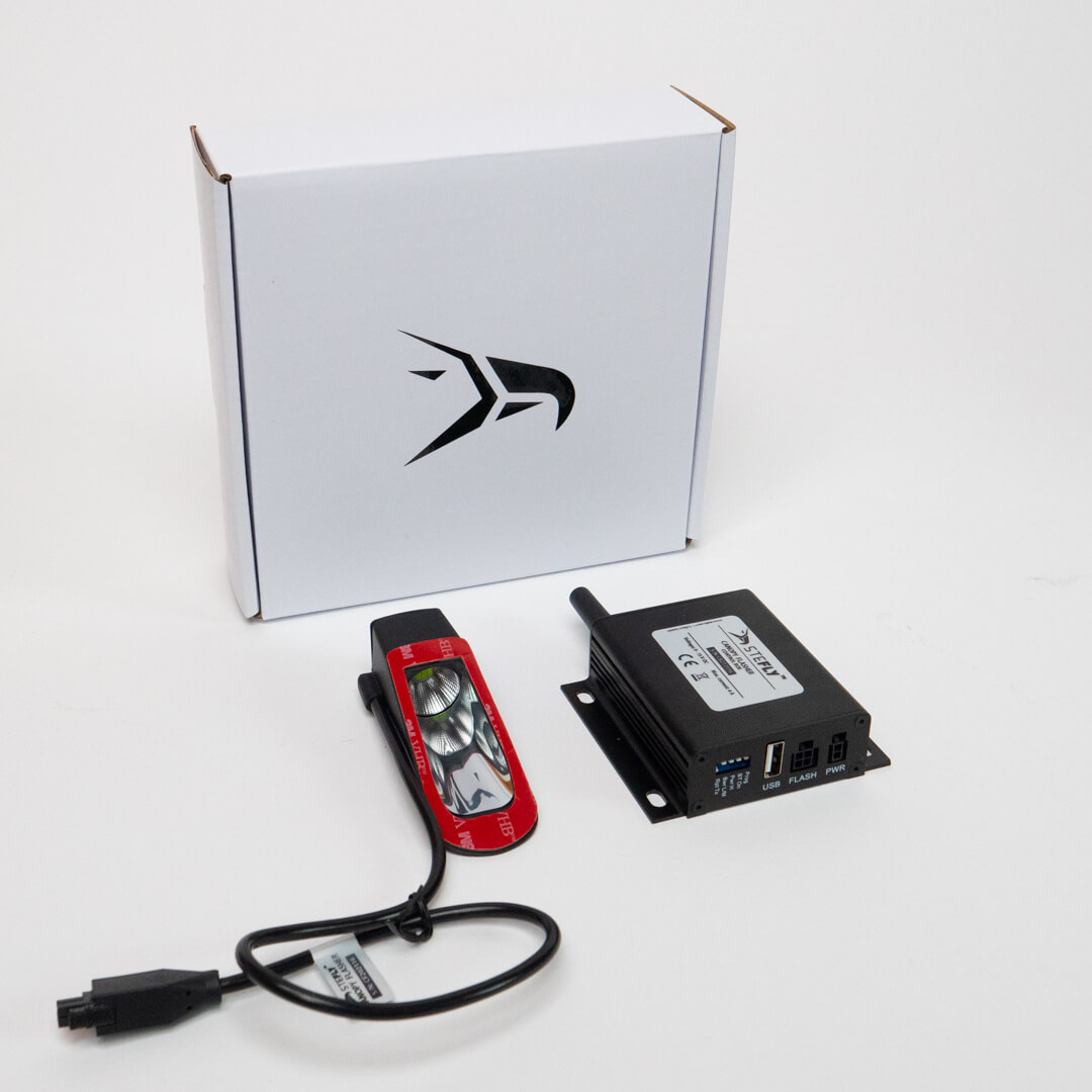
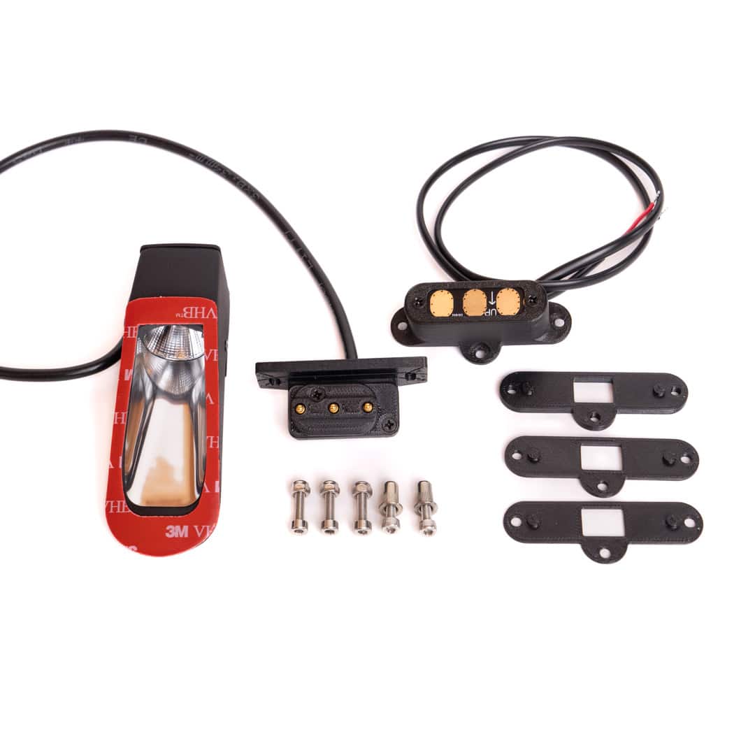
Scope of Delivery:
- SteFly Canopy Flasher with green LEDs and black aluminum / SLS-printed housing
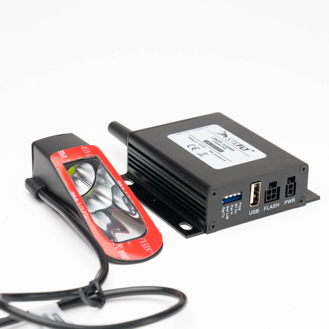
- Control Box for automatic on/off switching of the flasher when airborne and increasing of the flash intensity according to FLARM® collision warning data (not included in the scope of delivery of Canopy Flasher Essential!); with integrated USB charger 5 V / 2 A for mobile devices, Bluetooth® (can send FLARM® and position data to a mobile device) and WLAN (for updates)
- On/off switch with integrated 4 A fuse and labeling panel
- All required cables (12 VDC power supply to on-off switch / on-off switch to control box / control box to canopy flasher)
- Masking foil template for precise alignment of the canopy flasher in the direction of flight
- Yaw string with clear adhesive pad and alignment template
Delivery time: depending on the housing shape up to 4 weeks
Canopy Flashers for Gliders Rethought.
The road from the first definition of the development goals to the day of shooting for the product presentation was long. But now it's time: Give flight safety the green light and "cleared for departure" with the SteFly Canopy Flasher!
Canopy Flashers for Gliders Rethought.
The road from the first definition of the development goals to the day of shooting for the product presentation was long. But now it's time: Give flight safety the green light and "cleared for departure" with the SteFly Canopy Flasher!

The Basic Idea:
Collision Avoidance by Increasing Visual Awareness
There are several technologies for LED strobe lights on gliders available. Their purpose is to reduce the risk of collisions in the air. Common solutions are flashers integrated in the nose of the fuselage or in the leading edge of the fin, streamlined fairings with LEDs integrated for installation on the underside of the fuselage or ACLs integrated in the wing tips, as in motorized aircraft. An alternative are canopy flashers, suitable for a quick and uncomplicated retrofitting without having negative influence on aerodynamics.
Together with the Just Soaring development team (Just Soaring is also your contact for Canopy Flashers in USA), we asked ourselves the question: how can we make canopy flashers even better?


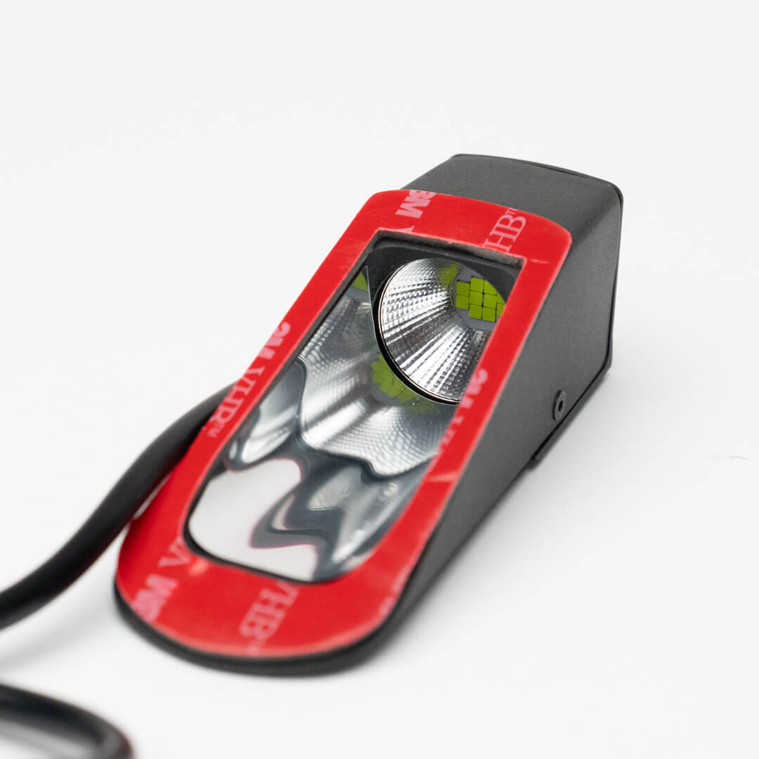
The result is a flasher that attracts attention: green light, central reflector, mirrored housing, slim housing shape and efficient cooling. In addition, there are many other detailed solutions to improve safety.

Highlights of Function and Design
- 10 green LEDs of the latest generation with a peak wavelength in the range of maximum perceptibility of the human eye
- strong luminous flux of 3600 lm
- The cone-shaped light beam formed by the reflector warns in particular oncoming aircraft
- At the same time, the high-performance LEDs produce enough light to widen the angle of reflected beam, so that aircraft appearing diagonally in front of your own glider are also warned
- To minimize the amount of light being absorbed by the housing, the housing is coated by a mirror foil. Therefore all the light coming out of the LEDs contributes to warn other pilots.
What Does a Canopy Flasher Help, if it Blocks the View?
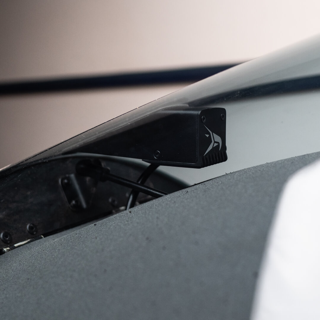
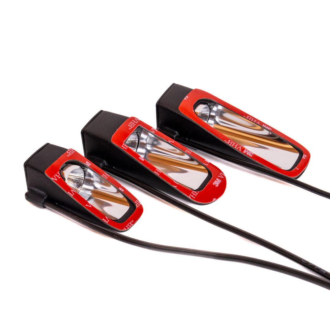
- New benchmark in terms of small housing width: with 26 – 33 mm, the field of view is hardly affected by the SteFly Canopy Flasher
- The housing width increases by 7 mm in the direction of flight, just as the light cone widens with increasing distance from the light source
- The slim form of the housing enables universal mounting on aircraft canopies with different curvatures


The problem of fogged up cockpit windows behind canopy flashers has been minimized
Under certain circumstances, an area with a fogged up window can form on the inside of the canopy behind the flasher. The reason is that the air flow from the front cockpit ventilation is obstructed by the flasher. The result is a dead water area formed behind the canopy flasher, in which water vapor condenses when the relative humidity in the cockpit is high and the outside temperature is low (e.g. at the cloud base). The forward visibility could be limited.
The slim design of the SteFly Canopy Flasher significantly reduces this risk. The air form the front ventilation flap is able to flow past the flasher housing to the right and left nearly unhindered and the dead water area is particularly small.
Aluminum Housing for Thermal Management
- - Milled aluminum heat sink for optimal cooling of the LEDs
- Perfect heat transfer for long LED life and high light output even in summer temperatures and high levels of solar radiation
- The front part of the housing is made by a 3D laser sintering process
- The housing of the flasher is black anodized and in the latest version contains a milled SteFly logo .
- Double-sided 3M-VHB tape for secure attachment of the canopy flasher on acrylic glass / PMMA; cut from one piece to keep stray light away from the pilot
- All SteFly canopy flashers delivered from February 2024 on have a small indicator lightintegrated into the heat sink, which lights up at the same time as the main LEDs. Therefore, the pilot can see live whether and at what rate the canopy flasher emits light. If necessary, the indicator light can be covered with the included cover cap.
Every glider is unique.
- With several housing shapes and a variety of canopy connectors, we offer solutions for a variety of aircraft types. And our range of products continues to grow.
- Inquiries for aircraft that are not yet listed in our standard range are welcome!
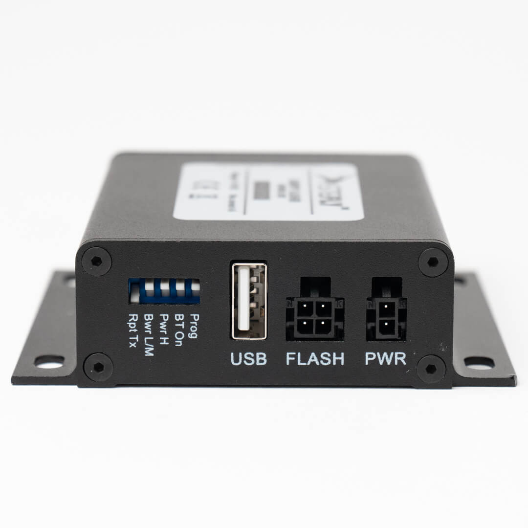
Control Box: Data Center, Security Gain and USB Charger all in One

- Evaluates FLARM® signals of aircraft in the surrounding area
- Ensures that the canopy flasher only emits light signals when the aircraft is flying, which prevents dazzling of start helpers or children on the ground looking directly into the canopy flasher
- Intensity of flash frequency increases, as soon as there is an airplane in the vicinity on potential collision course , which further increases the perceptibility

- Integrated Bluetooth module allows the transfer of FLARM®-data to mobile devices, so e.g. XC-Soar on the smartphone is able to show®FLARM traffic as well as your own GPS position e.g. in XC-Soar on the smartphone
- Thanks to Bluetooth Low Energy, this data can also be sent to Naviter SeeYou Navigator .
- In addition WLAN Both comfortable setting of the baud rate as well as firmware updates

- Basic settings can be configured manually via 5 DIP switches .
- In addition WLAN Both comfortable setting e.g. of the baud rate as well as firmware updates
- 2 amps USB-A power jack supplies external devices (e.g. smartphones) from the on-board battery with 5 V / 2 A. A power bank is no longer required.

On-Off Switch
- The included Switch needs to be integrated into the instrument panel to activate the flasher
- The switch module has an integrated 4 A fuse as well as screw terminals for the cables
- The package includes the required label in form of a black cover, which can be used also as drilling template

New to “Visual Awareness Lights”: The first green LED flasher for gliders

Relative brightness sensitivity curves describe how the human eye perceives brightness as a function of the light colour (red curve: perception during daylight; blue curve: perception in dimmed conditions)
Green for photometric reasons: Green is significantly brighter than red for the human eye. This is the reason why green LEDs are that efficient.
The goal: generate light with high efficiency instead of heat!
All 10 LEDs in the SteFly Canopy Flasher emit a large part of the radiation within a wavelength range of 490 - 570 nm. This wavelength range is therefore perceived by the human eye as very bright, which is synonymous with high efficiency. The relative brightness sensitivity curve shows that yellow-red LEDs (approx. 625 nm) only have a relative brightness of 0.35 compared to the green-yellow optimum. In order to generate the same brightness perceived by the human eye, a yellow-red LED (625 nm) must be supplied with around 2.8 times the power. With an even more intense red tone (e.g. 680 nm), the efficiency is even worse.

By the way: The manufacturers of construction and surveying lasers are also increasingly opting for a green instead of red laser color for their most powerful products due to the significantly better visibility.


Why does a Flarm connection to the canopy flasher make sense?
What is good for visual awareness also has a disadvantage: the more powerful the LEDs, the more care must be taken to ensure that no one (especially children) looks directly into the flash light from a short distance. We have therefore decided to only offer our LED flasher for gliders in combination with a control box. It evaluates FLARM signals and enables the LEDs to begin flashing automatically as soon as the aircraft is in the air. After landing, the canopy flasher switches off automatically. This only requires that the ACL switch on the instrument panel is set to "On". We deliberately did not use a control LED, which is usually attached to the back of the canopy flasher, to avoid reflections in the canopy. However, when the ACL switch on the instrument panel is flipped, the SteFly Canopy Flasher signals that it is working properly by two short, reduced-brightness flashes.
However, make absolutely sure that nobody is looking directly into the canopy flasher or into the reflected beam when the canopy flasher is switched on! This could possibly damage the retina temporarily or even permanently.
EASA believes that canopy flashers and other LED visual awareness lights contribute to flight safety and allows installation in accordance to EASA Standard Change CS-SC036b (INSTALLATION OF VISUAL AWARENESS LIGHTS). Accordingly, e.g. the effect on mass and center of gravity must be taken into account and the canopy must of course still be able to be ejected. The acceptance is carried out by an examiner.
Overview of the installation process:
- Determine the approximate position of the canopy flasher (ensure that the flap controlling the ventilation has enough clearance!)
- Degrease the canopy in the area of the adhesive surface (for the canopy flasher and the yaw string)
- Tension a thread from the nose of the fuselage to the top of the vertical stabilizer
- Use a measuring tape to align the thread in the middle of the canopy
- Optional: attach the yaw string using a template
- Stick the adhesive template with the outline of the canopy flasher on the outside of the canopy
- Remove the protective film from the canopy flasher and stick it to the canopy according to the template
- Position the on/off switch in the instrument panel
- The labeling board of the switch also serves as a drilling template (drilling diameter 6 mm)
- Fasten the control box in front of the instrument panel (screws and clamps / cable ties / Velcro)
- Plug in the cables and connect the cables to the screw terminals of the on/off switch
- Function test for the “Essential” version by switching the on/off switch
- Function test for the version with Control Box
- by switching on canopy flasher (it only flashes twice on the ground with low intensity and lights up at full brightness after taking off)
- repeated flashing, however, is triggered in the SteFly canopy flasher web application
- or, if Power-FLARM® is installed, you can simulate an approximation in the FLARM®simulator app
Quick and Easy Installation - Even During the Gliding Season
Degrease an aircraft canopy made of acrylic glass / PMMA / Plexiglas® only with water with dishwashing detergent, isopropanol or benzene-free petroleum ether, but never acetone or other alcohol as these solvents may cause micro cracks!
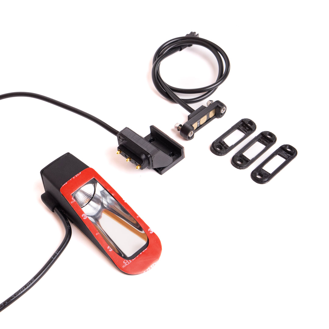
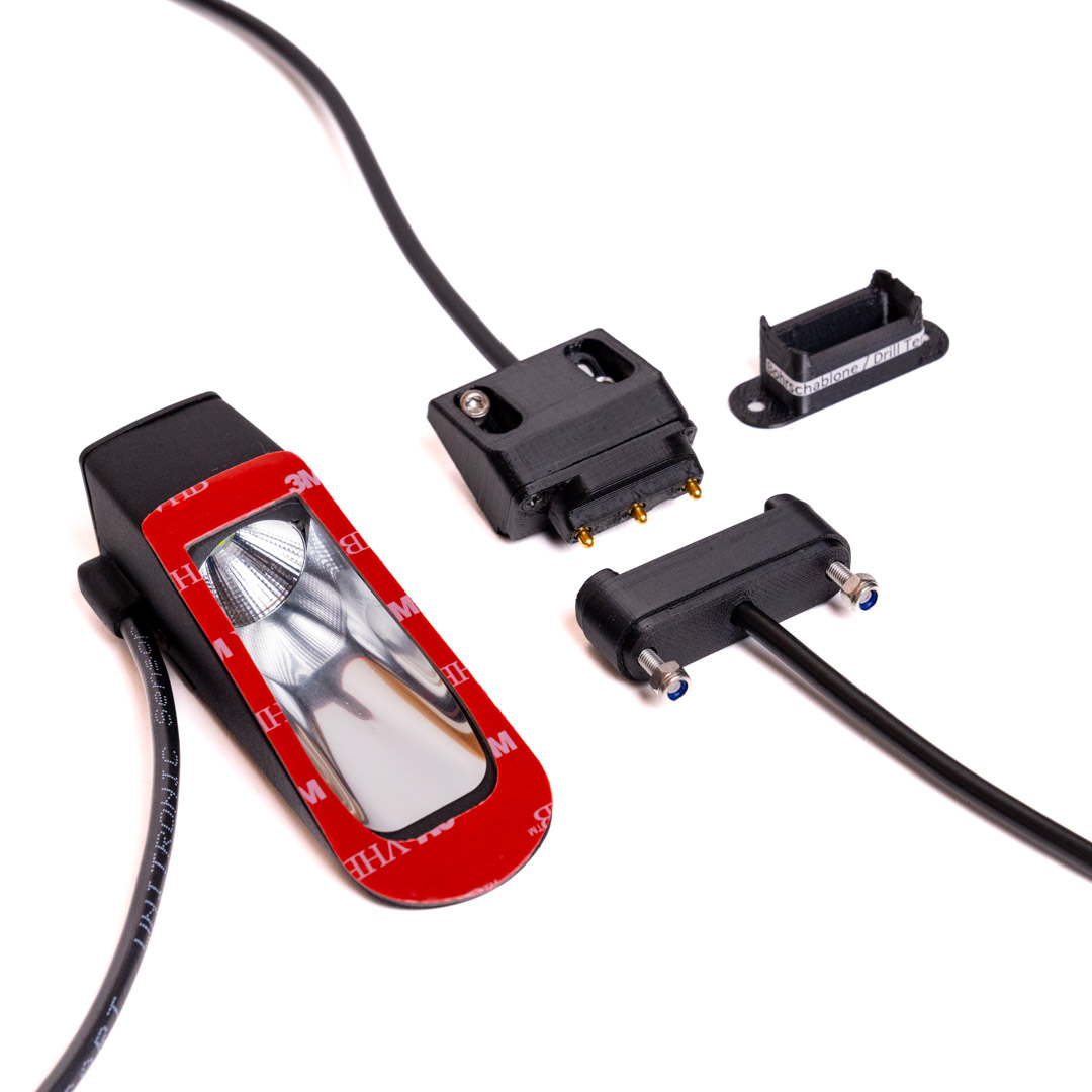
Canopy Contact for Side-Opening Canopies
For many glider models with canopies opening to the side, we offer special canopy contacts tailored to the respective aircraft type. This canopy opening mechanism is used in many Schempp-Hirth models (e.g. Discus, Ventus, Janus, Duo-Discus or Nimbus). But we also have sets in our program for aircraft from Grob (e.g. Twin 1 / 2/ 3, Astir) or DG (DG 500, DG 1000, DG 1001). Our range of offers is constantly expanding. All canopy contacts have three gold-plated, robust spring contacts in a housing that, depending on the model, is attached to the inside of the canopy acrylic glass using 3M VHB adhesive tape or to the canopy frame using threaded sleeves. The counterpart, consisting of a PCB with contact surfaces in a housing, is screwed onto the instrument panel cover. When the canopy is closed, electrical contact between the control box and the hood flasher is now established automatically.
Special Connector for the Canopy Jettison
On all aircraft types where the instrument panel is fixed to the canopy (e.g. Alexander Schleicher) or types where the canopy is hinged at the front (e.g. LS), the control box and canopy flasher may be connected with the cable included in scope of delivery, which has a special connector serving as predetermined breaking point.

When having selected the connectors we made sure that they separate automatically with little force in the event of an emergency release of the canopy. The locking lug has been removed as well. Therefore, please do not use cable ties to secure the plugged-in connectors and bind them together! Secure only the connector that goes to the control box, as this will remain connected to the aircraft even during canopy jettison.

If cable ties are applied during the canopy flasher installation, there must be provided a cable loop (at least 10 cm) in the area of the predetermined breaking point connector. The reason is that in the event of an emergency jettison, the canopy is now able to detach about 10 cm from the aircraft until the connection cable between Control Box and Flasher is fully tensioned. This ensures that canopy and fuselage disconnect from each other under all circumstances.
Installation / Operating Manual
The current version 1.5 (February 2024) of the instruction for installation and operation can be found here!
Installation Manual and Operating Instructions
Installation Manuals for Canopy Connectors
For side opening canopies with connector on the right side, e.g. Discus, Ventus, Janus, Duo Discus, Arcus, Nimbus, Pilatus B4:
DG doubleseater, e.G. DG 500, DG 1000, DG 1001:
Twin 1
Twin 2 and Twin 3
Astir CS

Update for Control Box
version July 2024
Technical Data
LEDs: 10 green LEDs, wavelength predominantly between 490 and 570 nm, 3600 lm
Canopy Flasher Standard Housing: mass 53 g (incl. 40 cm cabel), dimensions length x width x height 95 mm x 33 mm x 30 mm
Control Box: Gewicht 128 g, Abmessungen (ohne W-Lan-Antenne, mit Montageflansch) LxBxH 78 mm x 84 mm x 25 mm
On-Off Switch: mass 10 g, dimensions width x height 15 mm x 31 mm
Connection Cables: mass 57 g
Input voltage range: 9 to 15 V DC
Amperage: 80 mA for canopy flasher Essential @ 13,5 V
110 mA total for canopy flasher and Control Box @ 13,5 V and flashing frequency "low";
150 mA total for canopy flasher and Control Box @ 13,5 V and flashing frequency "medium";
additonal 20 mA when transferring data via Bluetooth
Interfaces: 2 serial interfaces: 1x FLARM®-input and 1 x FLARM®-repeater (e.g. for AIR Traffic Display or FLARM®-Display), Bluetooth, WLAN
USB: 1 USB-A Port, 5 V / 2 A for charging mobile devices
Operating Temperature: -30°C to +60°C
Material: Control Box housing and the heat sink of the canopy flasher are made of black anodized aluminum; housing of the canopy flasher made of SLS-printed plastic, painted matt black
Internal Fuse of the On-Off Switch: 4A
Recommended Accessories: USB-A panel mount adapter for the instrument panel (for better accessibility, if it is intended to use the integrated USB charger 5 V / 2 A)