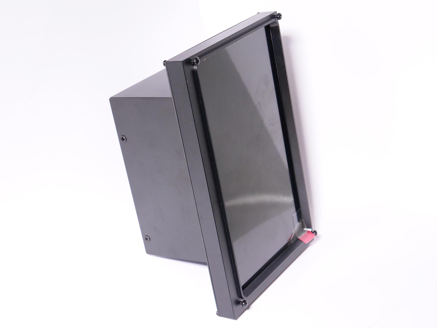
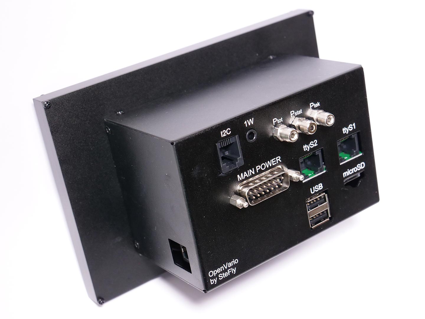
Assembly of OpenVario
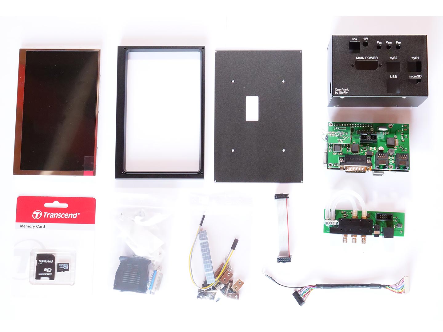
What is included in the OpenVario kit?

  • 5,7″ or 7″ housing
  • 5,7″ or 7″ display
  • Adapterboard with Cubieboard2
  • LVDS cable
  • Sensorboard connection cable
  • 4 Gb microSD card
  • Screws and small parts
  • D-Sub 15 connector

The sensor board is optional and not included in the scope of delivery of the OpenVario. An alternative to the sensorboard is LARUS, which can also be connected to the OpenVario. LARUS offers a high-end variometer for the dedicated cross country and competition pilot as well as real-time wind calculation.

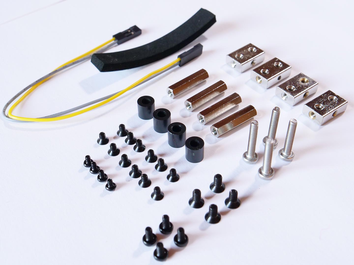
Small parts in detail

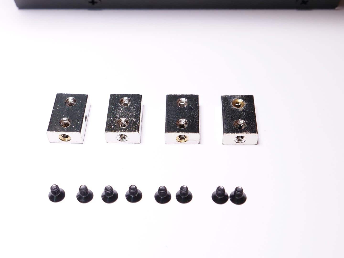
  • 4 x mounting brackets with M2.5 threads
  • 4 x plastic spacers
  • 4 x M3 distance bolts
  • 4 x long M3 screws
  • 4 x black M3 countersunk screws
  • 12 x black M2.5 countersunk screws
  • 4 x black M2.5 raised head screws
  • 4 x black M2 raised head screws
  • 1 x foam material

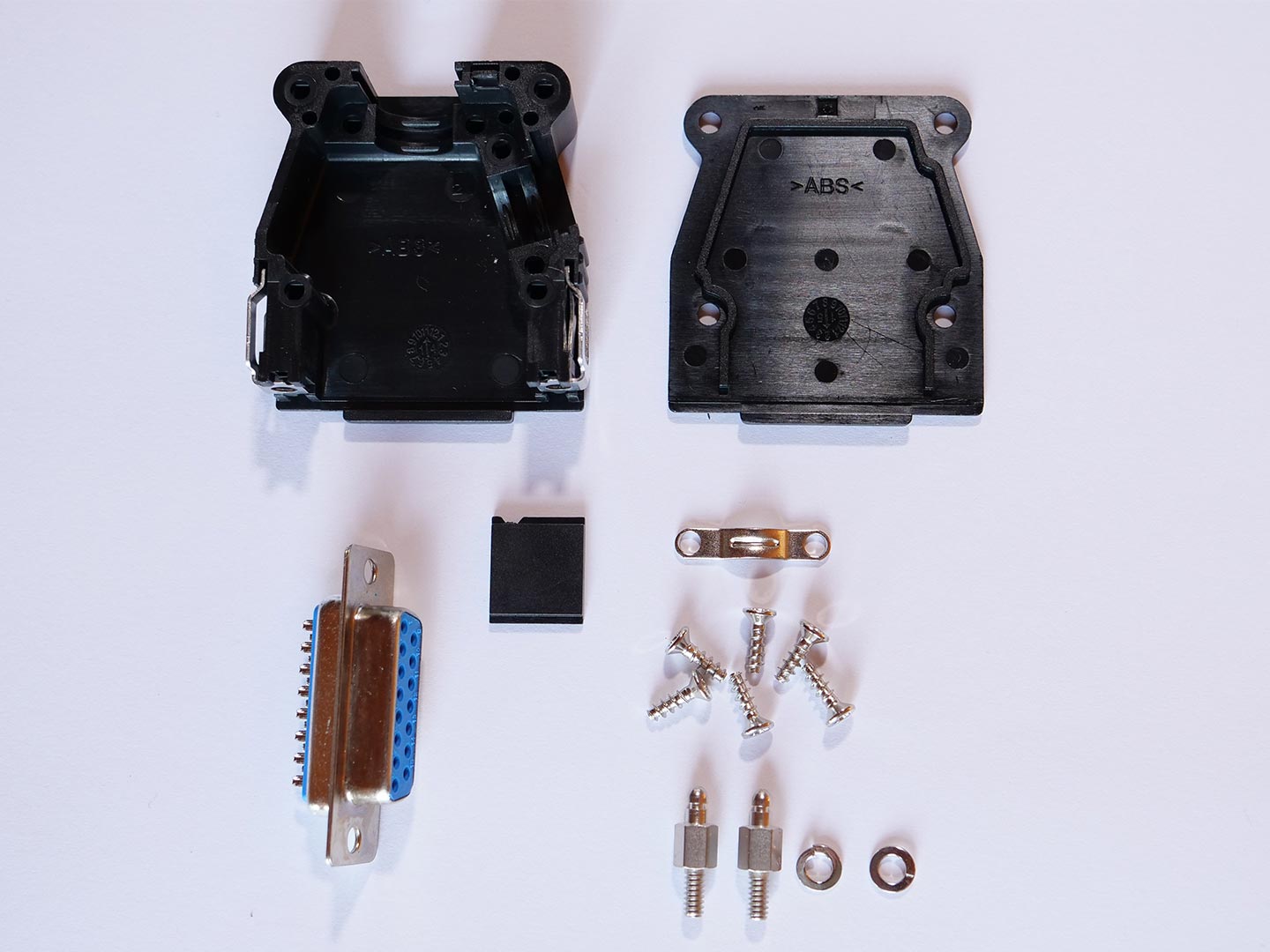
D-Sub Connector and Housing

  • D-Sub housing
  • D-Sub 15 female connector
  • 6 x screws
  • strain relief
  • 2 x quick lock bolts

Step 1: Mounting Adapterboard & Cubieboard

Parts required:

  • 4 x long M3 screws
  • 4 x plastic spacers
  • Adapterboard with Cubieboard
  • 4 x M3 distance bolts

Please note: Using threadlocking adhesive is not necessary. If you want to apply threadlocking adhesive, please use only low-strength versions like Loctite 221. Otherwise, disassembling is hardly possible!
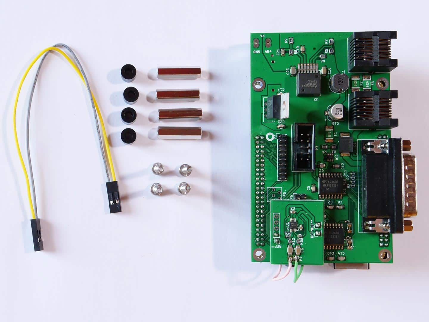
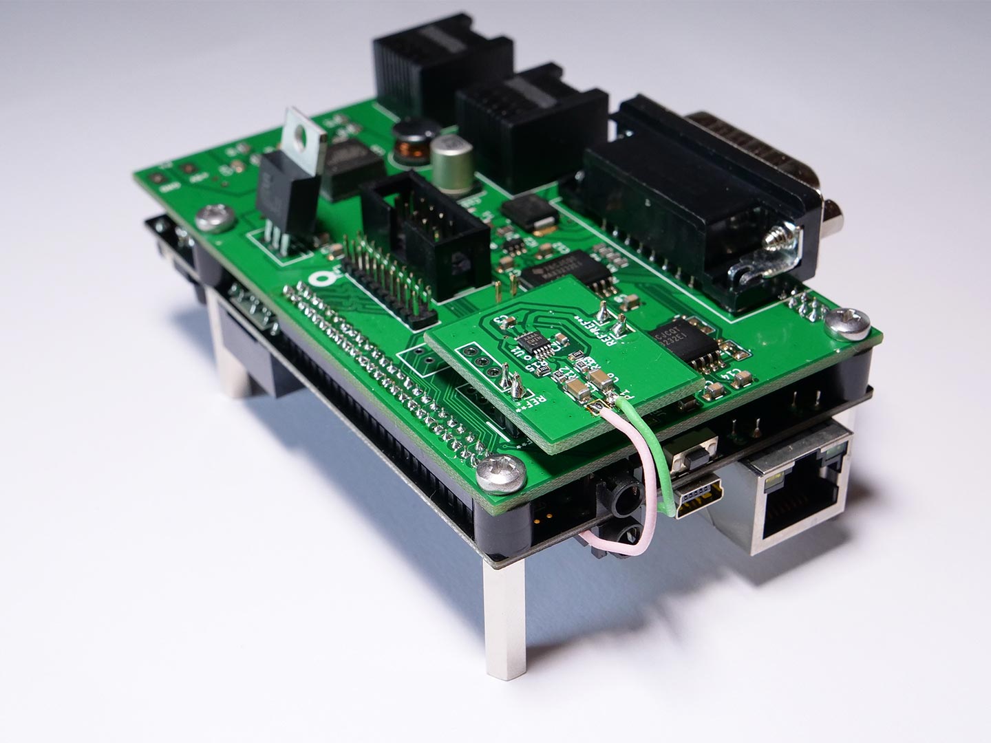
Step 1.1: Mounting Adapterboard & Cubieboard

Note: Please have a look at Step 6: In step 1.1 you should already attach the cable shielding (black wire with ring connector) of the display cable.

Mount the Adapterboard to the Cubieboard like shown in the picture. Be cautious when you need to readjust the distance between Adapterboard (green) and Cubieboard (black). Only apply force in the area of the pinheaders, so that you don´t bend the thin Cubieboard too much.

Step 1.2: Mounting Adapterboard & Cubieboard

Mount the distance bolts and spacers as shown.
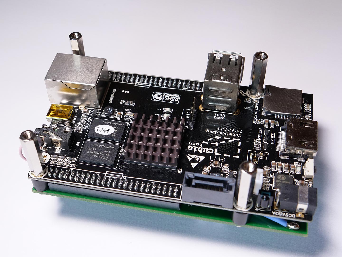
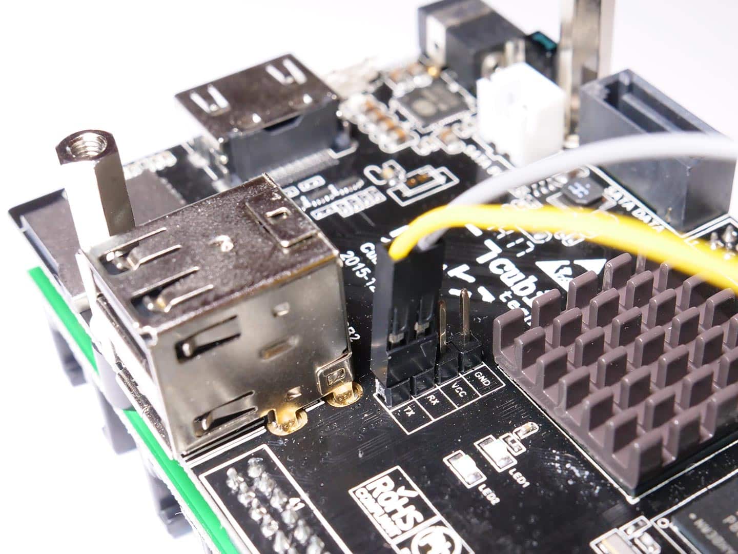
Step 2.1: Serial cable between Adapterboard & Cubieboard

Please note: Steps 2.1 – 2.3 can be skipped. Serial cables are not included in the kit any more on grounds of simpflification. Parts required:

Parts required:

  • Adapterboard & Cubieboard
  • 2 pin serial cable

Now you can attache the 2 pin serial cable between the Adapterboard & Cubieboard.

The Cubieboard has a pinheader with 4 pins, but we only use the RX and TX pin. Attache the cable to the RX and TX pin.

If you don´t install the serial cable, you still have 3 serial ports on the OpenVario for external devices. And at the moment, ttyS0 (UART 1) is only configured for debugging purpose.

Step 2.2: Serial cable between Adapterboard & Cubieboard

Now flip the package, so that the Adapterboard is on top. There you will find a 2 pin pinheader, which is located in the middle of the Adapterboard. Connect the cable here, so that you don´t twist the cables. In this example the yellow cable is on the side of the USB port. The colour of the cable can be different in your OpenVario kit.

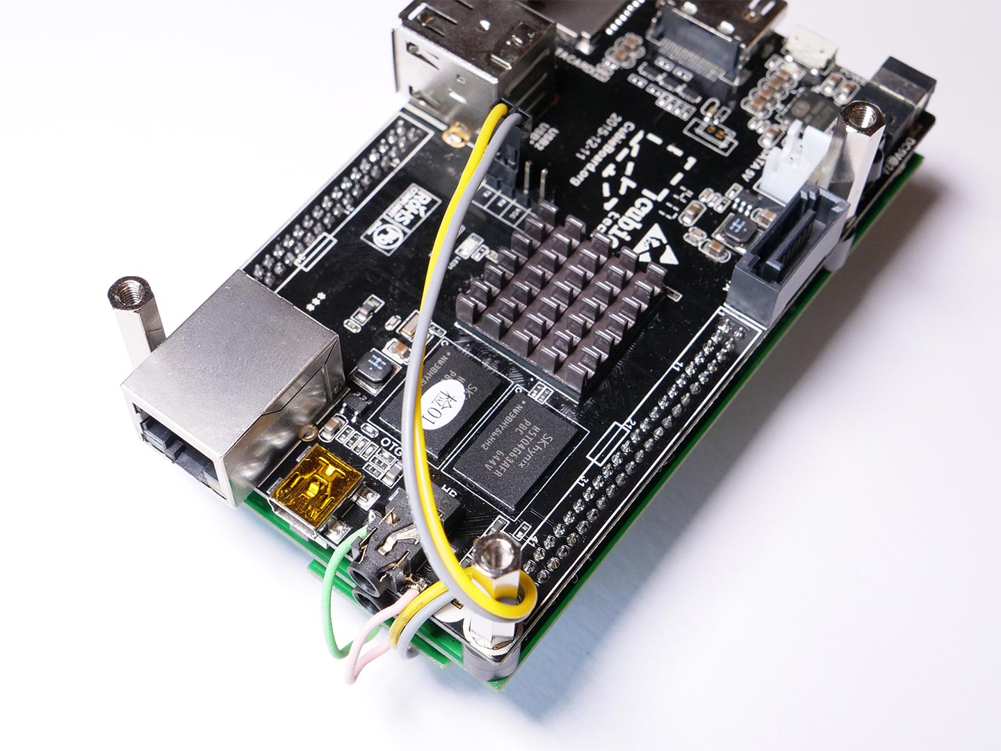
Step 2.3: Serial cable between Adapterboard & Cubieboard

You can wind the serial cable around the distance bolt like shown in the picture.

Step 3: Sensorboard installation (optional)

Parts required:

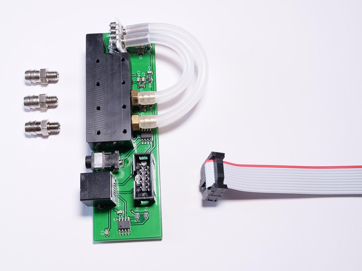
  • Sensorboard
  • 3 x hose connectors
  • Sensorboard cable
  • Back housing of the OpenVario

Install the Sensorboard cable on the IDC header of the Sensorboard like shown in the picture.

Step 3.1: Sensorboard sealing

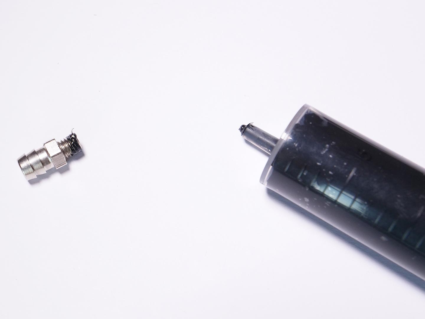
Please note: Sealing of the hose connectors of the sensorboard is highly recommended to ensure the air-tightness.

Take some Sikaflex 221 or similar silicone free sealant and put it on the threads of the three hose connectors. Be careful not to use too much, otherwise it will squeeze out and can close the pressure hole.

Step 3.2: Sensorboard sealing

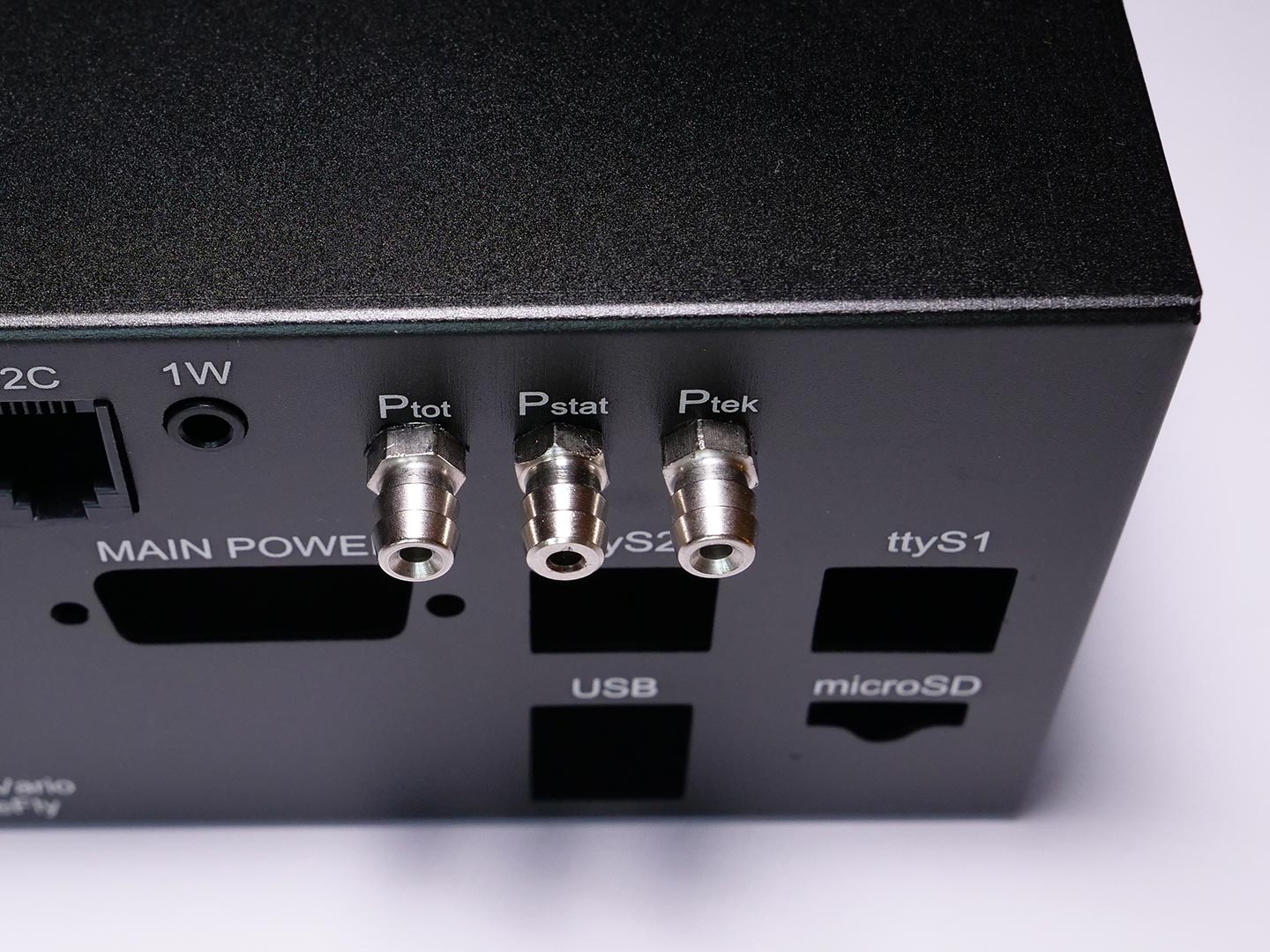
Now you can carefully insert the Sensorboard into the housing. Look at the correct alignment before you fasten the hose connectors.

Step 4.1: Mounting Adapterboard & Cubieboard in housing

Parts required:

  • Adapterboard & Cubieboard
  • 4 x M3 countersunk screws
  • 2 x quick lock bolts
  • Rear housing

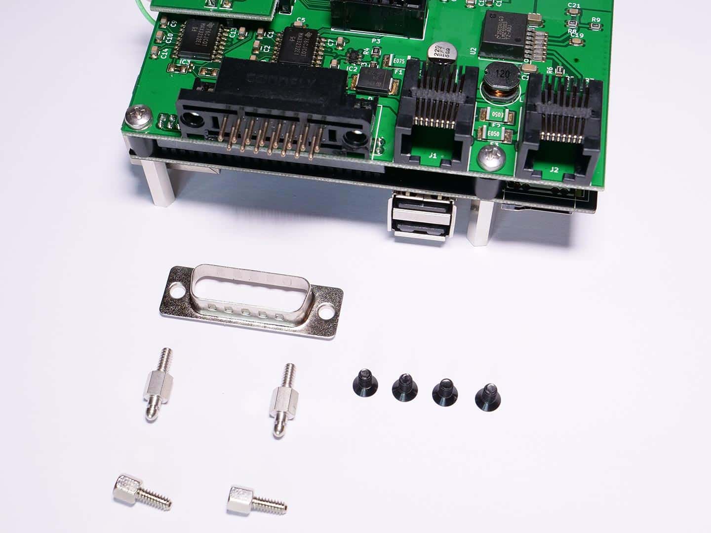
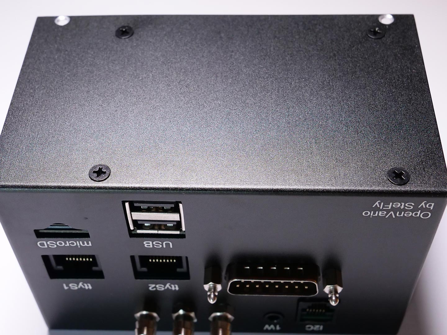
Before installing the Adapterboard & Cubieboard package in the housing, you need to unscrew the distance bolts on the D-Sub 15 connector. The loose metal cover should stay on the connector in the correct direction. The original distance bolts are not needed anymore and replaced by the quick lock distance bolts.

Step 4.2: Mounting Adapterboard & Cubieboard in housing

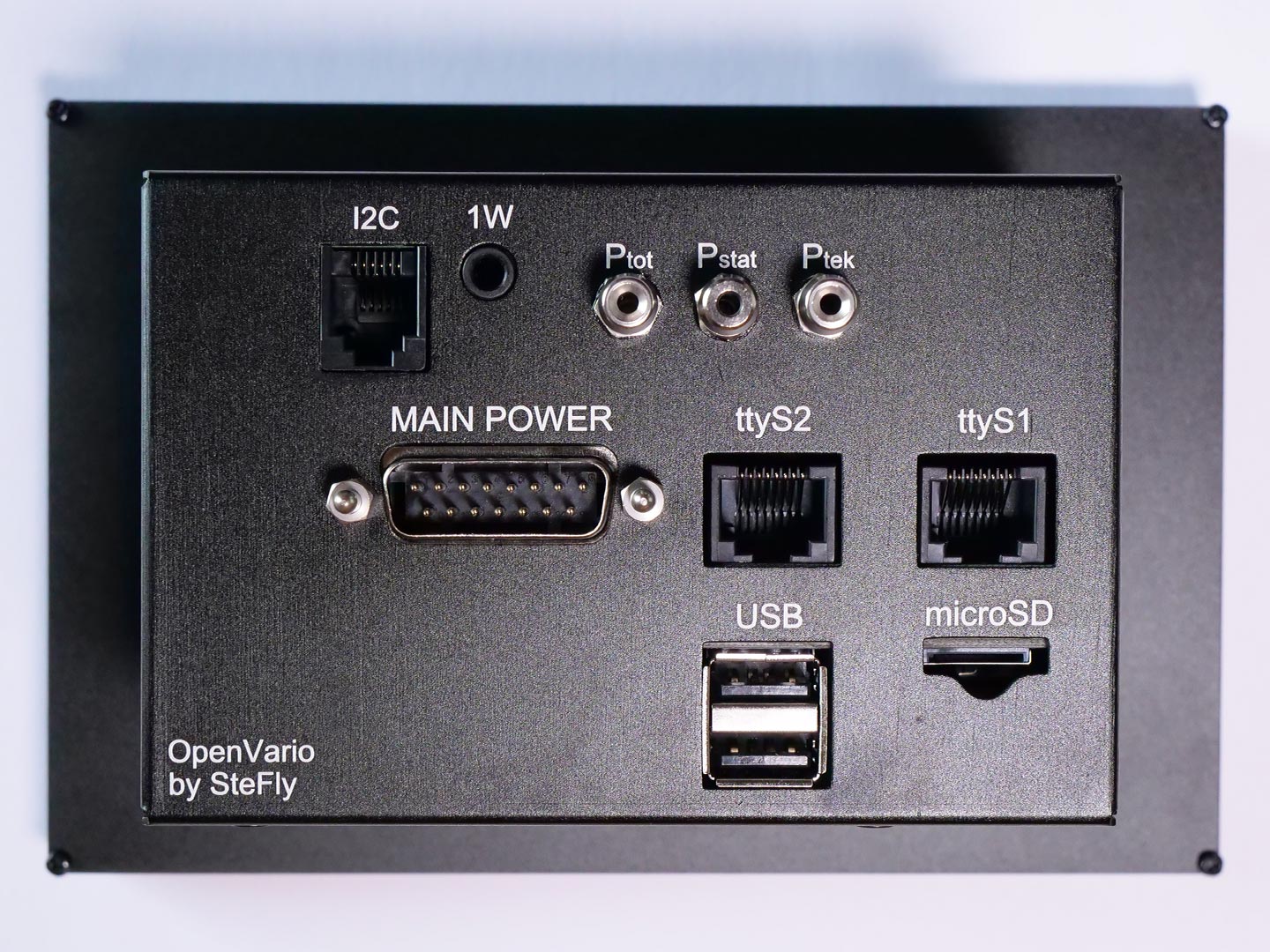
Insert the Adapterboard & Cubieboard package into the rear housing box, so that the connectors at the back side matches the holes. Take care of the loose metal part from the D-Sub 15 connector. When everything looks fine, you can screw in the 4 black M3 countersunk screws. After that, you need to install the quick lock distance bolts at the D-Sub connector.

Step 4.3: Install sensor cable

Install the sensorboard cable like shown in the picture.

Step 5: Installing mounting blocks

Parts required:

  • 4 x mouting blocks
  • 8 x M2,5 black countersunk screws
  • Rear housing

Step 5: Installing mounting blocks

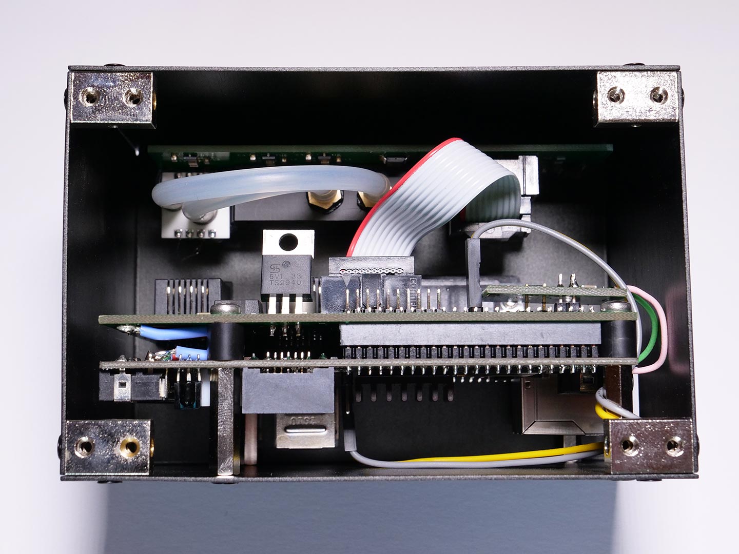
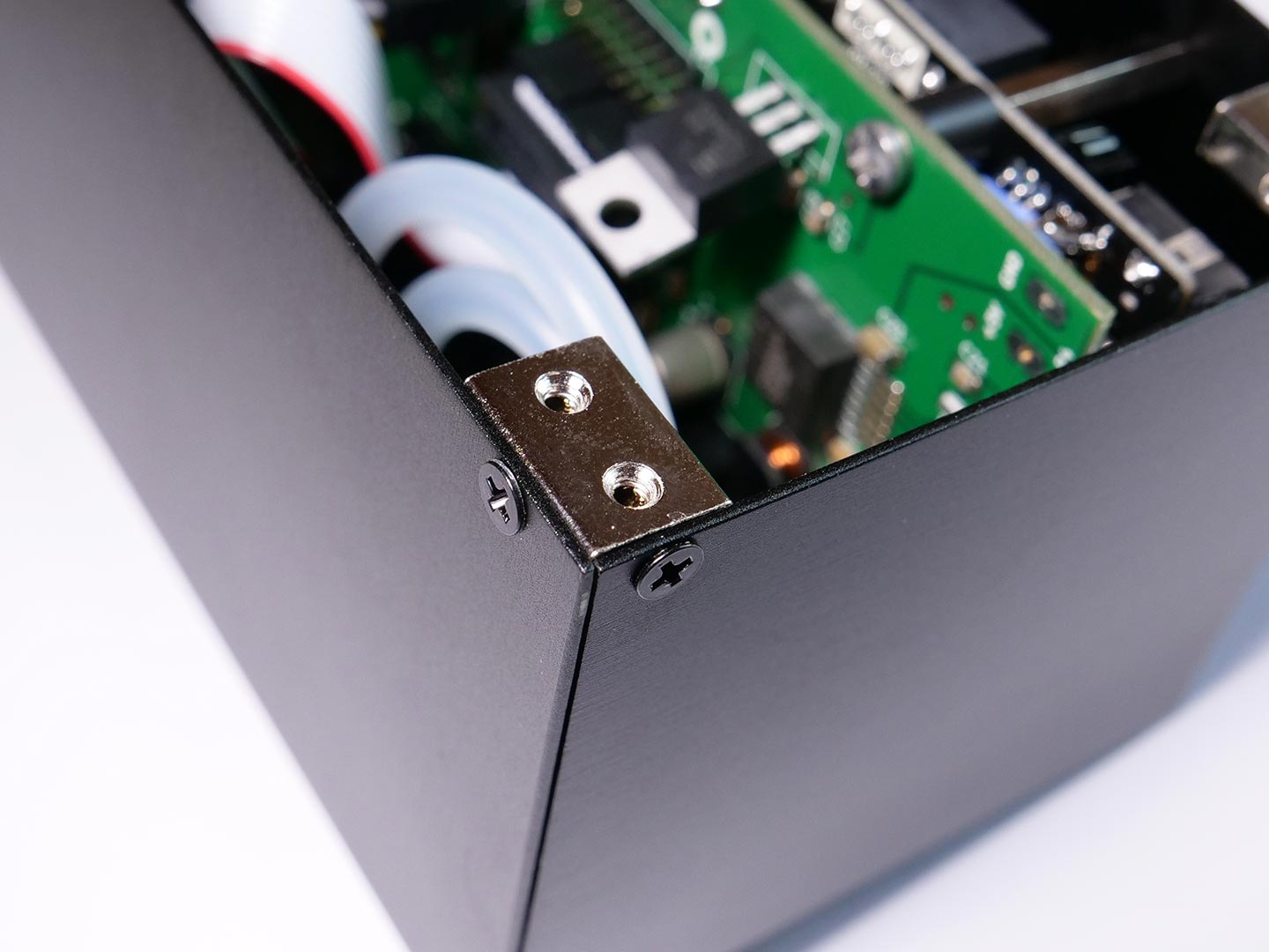
Install all four mounting blocks like shown in the picture.

Step 5: Installing mounting blocks

Here is another detailed picture.

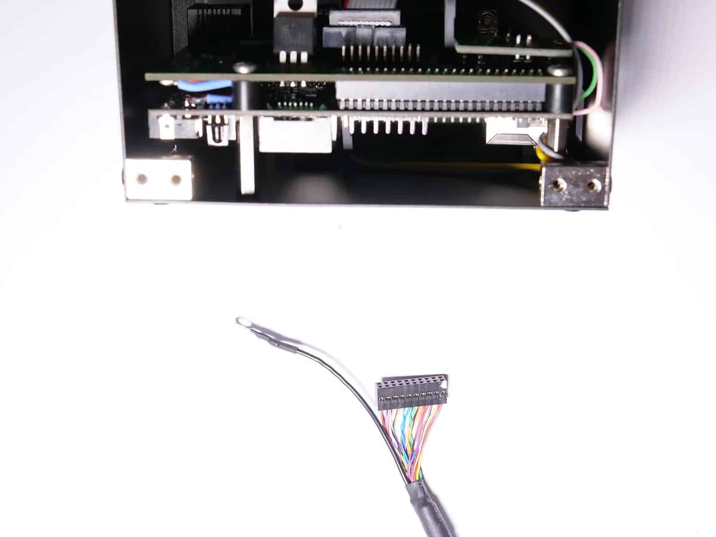
Step 6: Connecting Displaycable to Adapterboard

Parts required:

  • LVDS displaycable
  • Back housing with electronics

Step 6: Connecting Displaycable to Adapterboard

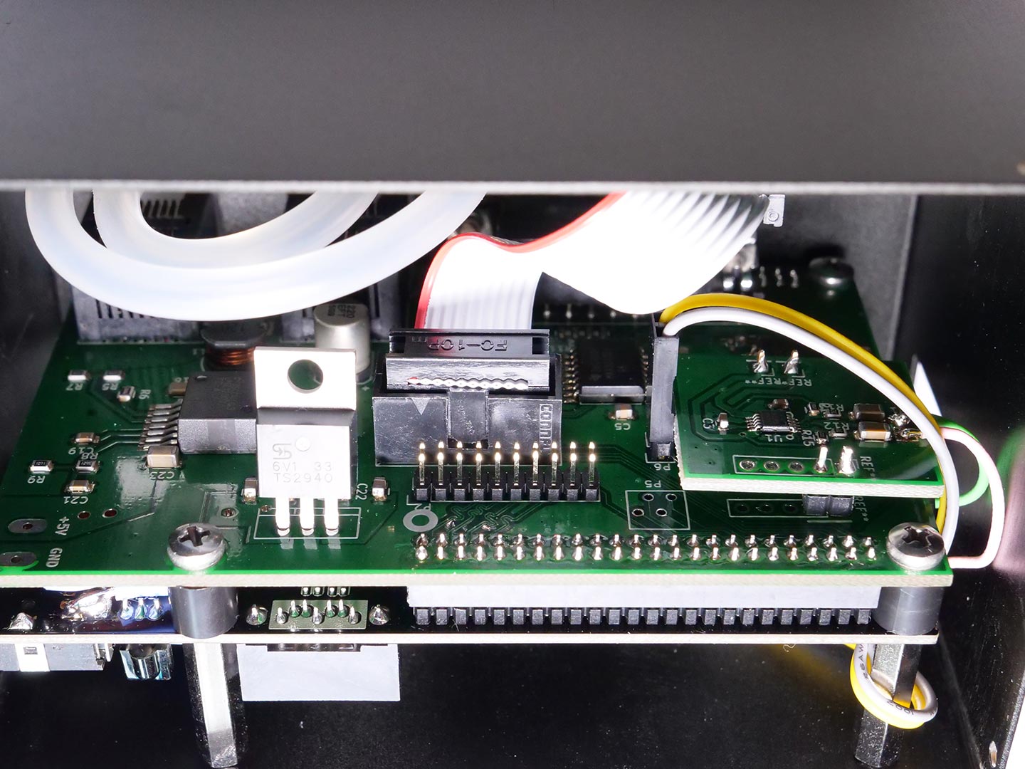
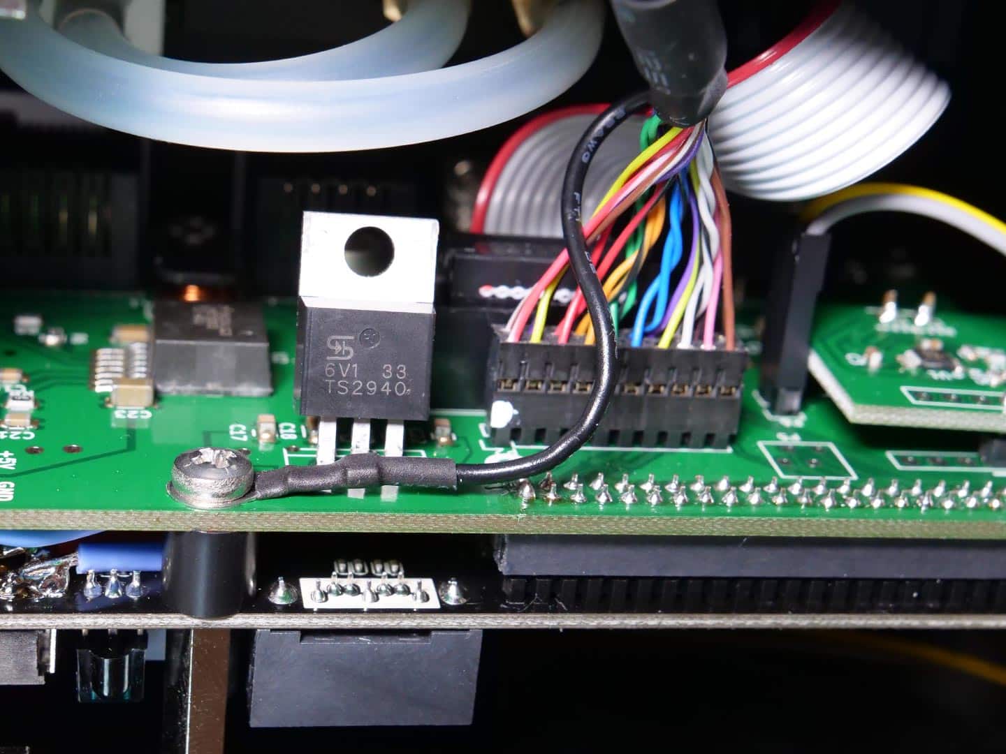
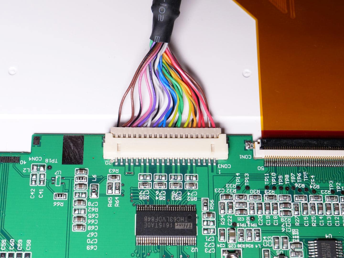
Plug in the display cable connector to the adapterboard like shwon in the picture. Take care of the orientation!! There is one whit dot at the connector housing and one white circle at the adapterboard for orientation. In this picture, the white dot is at the left side of the display cable connector.

Also attach the cable shielding (black wire) to the screw like shown in the picture.

Step 7: Attaching front plate

Parts required:

  • Front plate
  • Back housing with electronics installed
  • 4 x M2,5 black countersunk screws

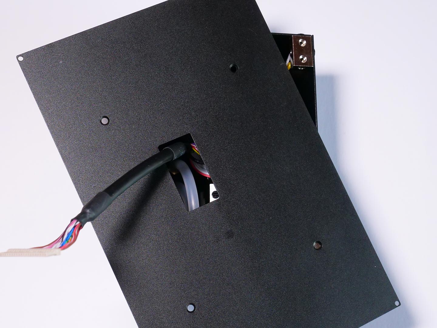
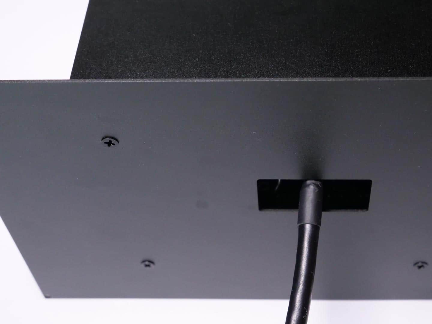
Install the front plate so, that the countersunk holes are looking to you. It is very important that the rectangular cutout for the displaycable is matching the display connection at the display. The cutout is not in center!
Please follow these steps:

  • Back housing in landscape orientation and lables are readable (not upside down)
  • rotate the front plate so that the cable cutout is more upper
  • Afterwards the front frame / display combination will be attached in a way that the bigger front border is at the bottom

Step 7: Attaching front plate

Mount the front plate with 4 x M2.5 black countersunk screws in the correct orientation.

Step 7: Installing display in front frame

Parts required:

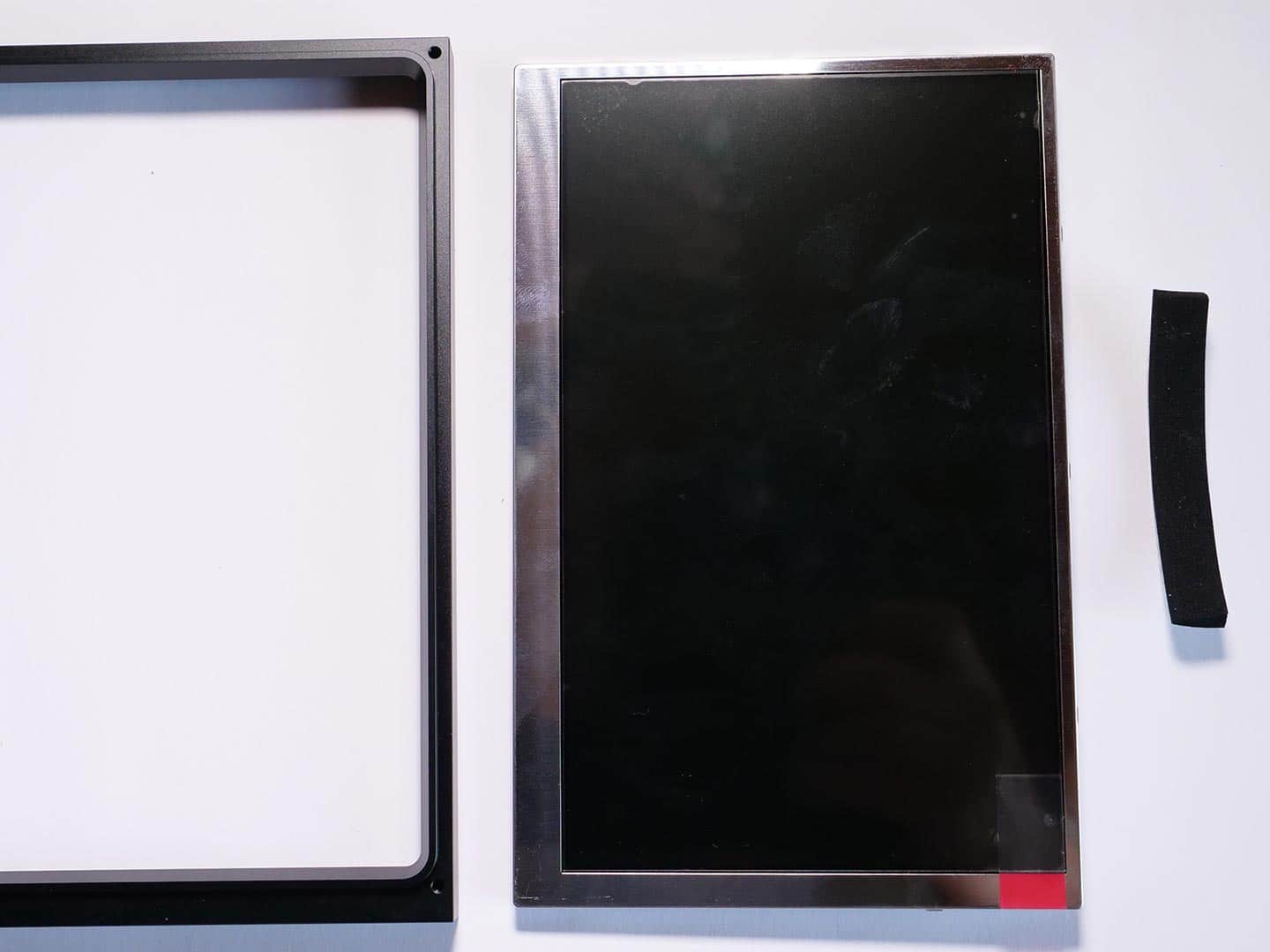
  • Front frame
  • Display
  • Foam strip

Step 7: Installing display in front frame

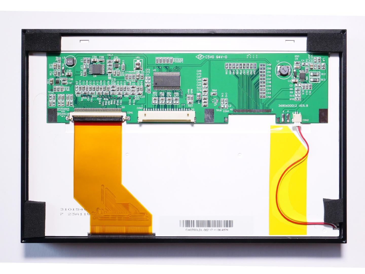
Install the display in the front frame, so that you can´t see the metallic display cover within the frame at the front side.

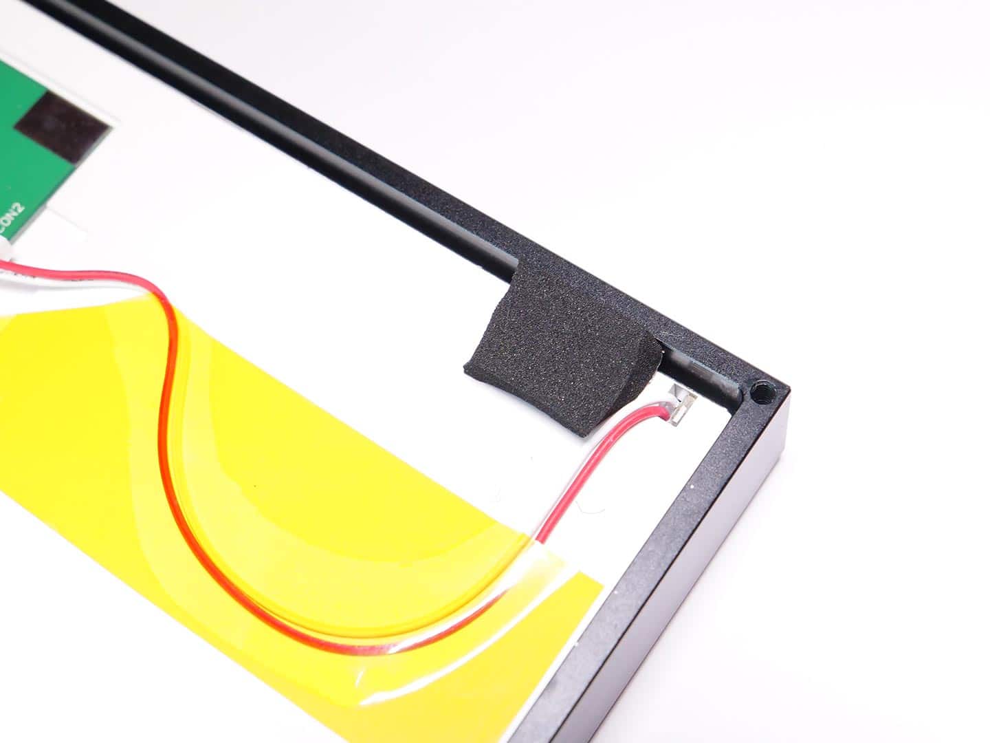
Now cut the foam strip in 4 small strips and attach them like shown in the picture.

Step 7: Installing display in front frame

At the corner with the white and red wire, we recommend to put the foam strip not above the cables.

Step 8: Installation of display cable at display side

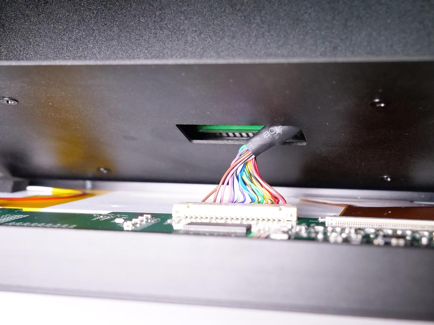
Insert the display cable in the display connector. Take care to install it in the correct orientation.

Step 8: Installation of display cable at display side

The installed displaycable should look like this.

Final assembly of housing

Now you can make the final assembly of the back and front housing. Take care to use the correct orientation, so that the display connector and the cutout at the front plate are matching. For more details read again Part 7.

Carefully put the stiff cable into the back housing, so that there is no stiff shielding left between display and front plate.

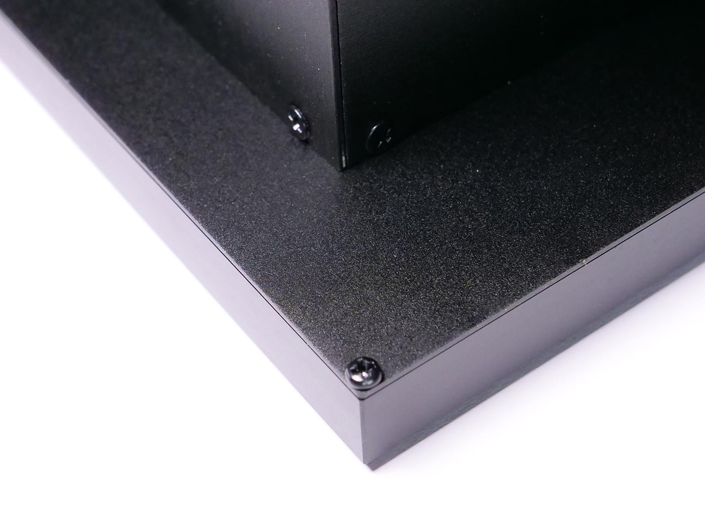
At the end you take the 4 x M2,5 black countersunk screws and install them at the corners.

Congratulations! That´s it with the mechanical assembly and you should now proceed soldering the D-Sub 15 connector, unless you ordered a "Wiring Harness with Loudspeaker" .

Cookie Consent with Real Cookie Banner