LARUS Gliding Sensor Unit
1.292,34 € – 2.082,50 €
incl. VAT plus shipping
LARUS sensor unit in aluminum housing. A separate display device such as the LARUS Vario Display, a SteFly NAV, an OpenVario or a Bluetooth-enabled device (smartphone / tablet) with XCSoar / OpenSoar is required to display the data.
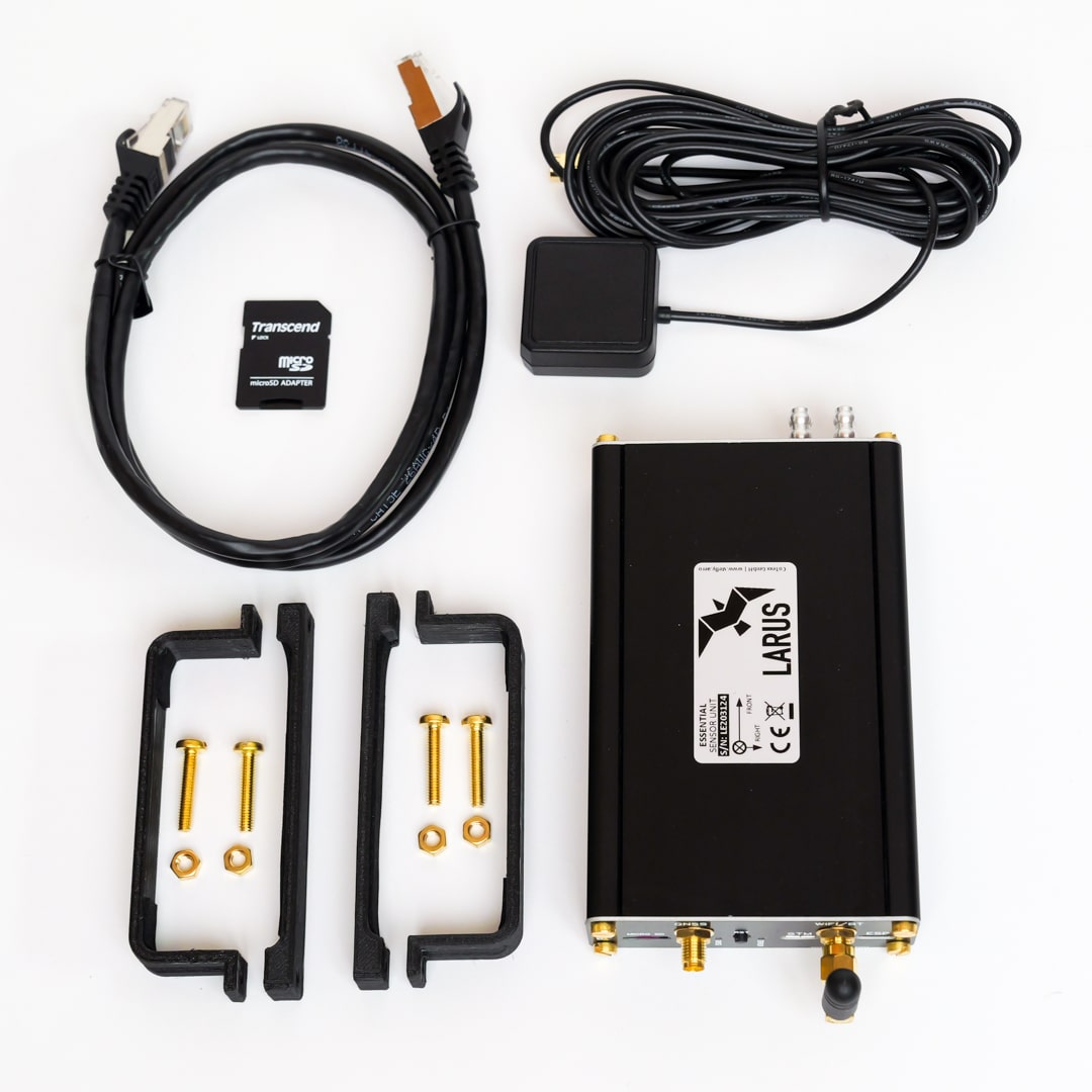
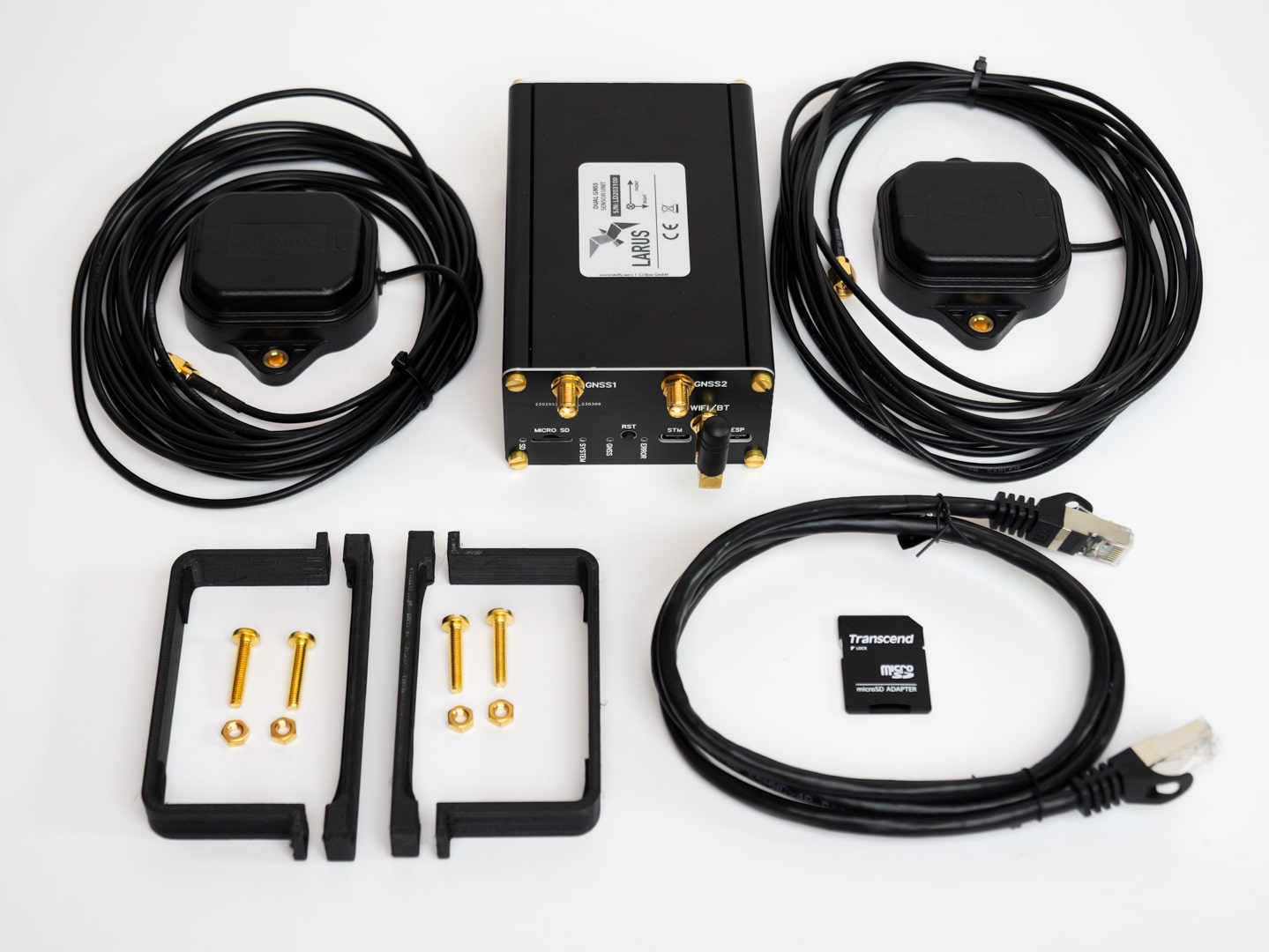
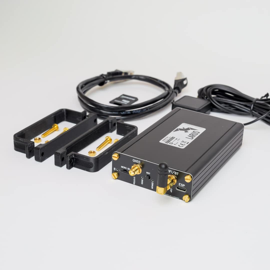
- LARUS sensor unit in black anodized aluminum housing
- 1 GNSS antenna (LARUS Essential) or 2 GNSS antennas (LARUS Dual-GNSS)
- Brass mounting screws and nuts
- 2 Fastening clamps
- min. 32 GB micro SD card with adapter
- RJ45 cable
Delivery time: 5-7 Werktage / Business Days
High end variometer. Precise real-time wind determination. Artificial horizon.
SteFly produces and distributes the high-end variometer under license developed by the LARUS project team led by Prof. Dr. Klaus Schäfer, Horst Rupp and Maximilian Betz.

In short: Data from one (or two) GNSS receiver(s), an IMU (inertial measurement unit) and pressure sensors for static pressure and dynamic pressure are combined and evaluated in the LARUS sensor unit using special algorithms. The results are transferred to a display device via a serial interface or Bluetooth. For example, all OpenVarios or other devices running XCSoar are compatible with the LARUS sensor unit.
- Energy-compensated climb or sink (variometer)
- Horizontal wind speed as an instantaneous value (live / real-time wind) and a value averaged over an adjustable period (e.g. 30 s)
- Attitude for display in an artificial horizon
- Pressure altitude / flight level FL
- True airspeed (TAS)
- Course over the ground (track)
- Drift angle (difference between track and heading)
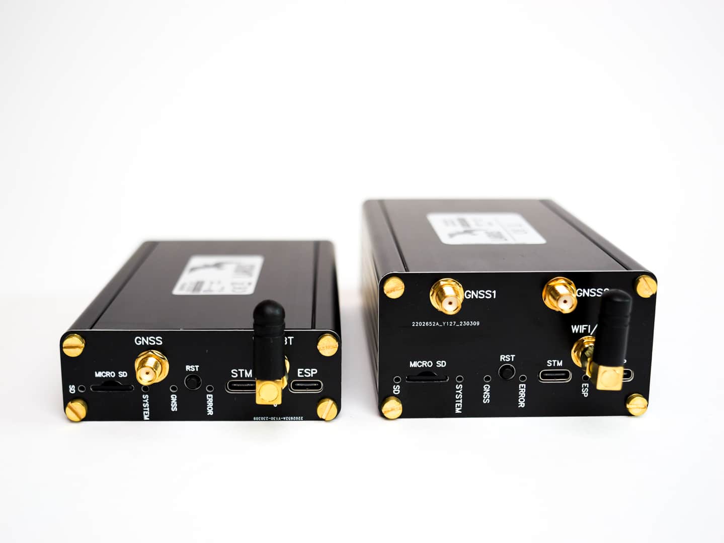
In the Essential variant, LARUS has installed a precise GNSS receiver with an external active antenna. In the LARUS Dual-GNSS variant, on the other hand, a high-precision dual-band receiver is connected to two active, multi-frequency band antennas.
GNSS
In recent years, location determination using GNSS (Global Navigation Satellite System) has become much more accurate. Because GNSS also includes satellites from GLONASS, Galileo and BeiDou in addition to GPS satellites, the modern GNSS receivers installed in the LARUS sensor box can achieve a horizontal positioning accuracy of 1.5 - 2 m. In addition, the ground speed is measured three-dimensionally and used to support the flight attitude measurement and as a measured variable for the variometer.
The accuracy of the speed measurement is:
- LARUS Essential with uBlox M9N single-frequency receiver and GNSS antenna: horizontal approx. 0.1 km/h; vertical approx. 5 cm/s
- LARUS Dual GNSS with uBlox F9P dual GNSS receiver: horizontal approx. 0.05 km/h; vertical approx. 2.5 cm/s


With LARUS Dual-GNSS, the accuracy of the heading can be improved to approx. 0.05 degrees by using a D-GNSS "compass" (2 coupled differential GNSS receivers, here uBlox F9P).
The flight attitude measurement can be used for an artificial horizon as well as for the precise display of the current drift angle (track – heading).

IMU
Inertial Measurement Unit (IMU) describes an inertial measurement unit that combines several inertial sensors. LARUS relies on the high-quality IMU XSENS MTi-1. It measures three-dimensional acceleration, yaw rate and magnetic field.
The flight attitude is calculated from this data by comparing it with the speed data of the GNSS (AHRS function).
When circling, the heading is determined by comparing the acceleration (determined from the flight path using the GNSS positions) and the AHRS. You don't need a magnetic compass for this. The Larus sensor unit automatically determines the calibration of the magnetic compass during circling flight, so that it can then be used to measure the magnetic heading in straight flight. Together with the adjustable magnetic declination, true heading (relative to true north) can be measured with an accuracy of about 1-2 degrees.

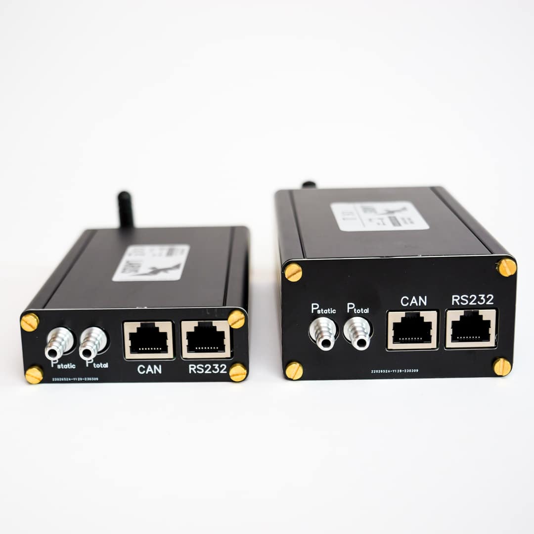
Pressure Sensors
The Larus sensor box contains pressure sensors for measuring static pressure and dynamic pressure. The static pressure is required to display the pressure altitude and the flight level FL. It is also used to determine air density.
The indicated airspeed IAS is formed from the dynamic pressure.
The true airspeed TAS is calculated from the indicated airspeed, taking into account the current air density. LARUS calculates the air density in real time by comparing the GNSS altitude with the pressure altitude, without having to measure the temperature or humidity. LARUS then uses the TAS to calculate the wind speed.


GNSS Antennas
The rear GNSS antenna cannot be installed in the luggage compartment area of aircraft with CFRP fuselage tubes. We have therefore developed and tested several alternative options, e.g.:
- For self-launchers and gliders with retractable engines, install the antenna in the engine compartment if the engine cowlings are made of GRP or can be modified retrospectively.
- Attachment of a special canopy antenna
- Attachment of a special, teardrop-shaped external fuselage antenna
An antenna splitter can be used to make the signals from a LARUS GNSS antenna available to the FLARM. This saves one antenna.

- The proven standard solution for excellent GNSS reception
- Ideally, the ground plate included in the scope of delivery should be mounted.
- With slight losses in reception quality, however, a smaller metal sheet can also be used as a ground plate, or an additional ground plate can be completely eliminated.

- The solution for aircraft with CFRP fuselage tubes in which the rear antenna cannot be mounted in the luggage compartment or no other suitable mounting location can be found that is sufficiently distant from other GPS antennas (Flarm).
- Mounted on the inside of the cockpit canopy using 3M VHB adhesive tape
- The low design and installation position at the rear end of the canopy above the pilot's/co-pilot's head provide optimum headroom and do not restrict visibility.
- A ground plate is essential. If the ground plate included in the scope of delivery cannot be installed, a smaller one may be used instead. The minimum requirement is to cover the entire underside of the plastic housing with a metal foil.

- The solution for the rear dual GNSS antenna when mounting the canopy antenna is not an option
- Mount the external antenna centrally on the fuselage spine behind the cockpit using 3M VHB adhesive tape.
- Negligible effect on aerodynamics
- The antenna cable to the LARUS box is fed through a 3.3 mm diameter hole in the fuselage shell.
- A ground plate is not required, as the CFRP fuselage shields interference signals from inside the fuselage.
Algorithms
Calculation of (real-time) wind speed
LARUS determines the wind speed from the three-dimensional difference between ground speed and flight speed. Both a short-term mean value and a long-term mean value are output. The periods differ as follows:
- In straight flight, the time period for short-term wind is 5 s and for long-term wind 30 s (default setting; both times are configurable)
- When circling, the short-term wind is the mean of the last circle, while the long-term wind is the accumulated mean over the entire time of the last circling phase

A special algorithm detects and eliminates deviations in circular flight that result from a change in the angle of attack.
With the introduction of the LARUS Vario display, all information can now be displayed clearly and attractively on a separate round instrument. The round display with a diameter of 57 mm offers plenty of space.
LARUS Sensor Box and LARUS Vario Display can also be installed as a stand-alone unit. A navigation computer or smartphone with XCSoar / OpenSoar is not required in this case.
Variometer
The LARUS sensor uses a Kalman filter to combine GNSS altitude, GNSS speed and vertical acceleration determined by the Inertial Measurement Unit (IMU).
This algorithm has virtually no inertia and provides a highly accurate (uncompensated) variometer instantaneously and without using pressure data.
The speed compensation is generated by differentiating the speed through the air. For this purpose, the ground speed of the GNSS and the average horizontal wind speed are used to calculate the kinetic energy of the three-dimensional movement.

OpenSoar with LARUS driver
The variometer display familiar from XCSoar accesses the LARUS data via the RS232 interface. OpenSoar / XCSoar continues to generate the vario sound.
Two separate wind arrows can be displayed directly in the moving map. This visualises the direction and strength of the current wind and the average wind over a longer period of time. In addition, new wind-related info boxes are available in OpenSoar.
Another novelty is the artificial horizon, which is displayed on a separate page in OpenSoar. It is helpful, for example, to check the correct function and calibration of the IMU after installing the sensor unit.


Installation Instructions
- Mount the sensor unit absolutely fix so that the position of the sensor unit in relation to the aircraft structure does not change under the influence of acceleration forces
- The LARUS sensor must be positioned as far away as possible from magnetic fields and bigger iron parts
- The installation orientation of the LARUS box is possible in all directions and only needs to be adjusted in the configuration file "sensor_configuration.txt". Nevertheless, we recommend to select the orientation with regard to the longitudinal axis of the aircraft during assembly according to the coordinate system printed on the LARUS housing. Ideally, the LARUS sensor unit is also mounted in such a way that it is roughly horizontal in normal flight and that the SD card remains accessible.
- The GNSS antennas must be mounted in such a way that there is ‘visual contact’ with as many satellites as possible. This means that they should be positioned approximately horizontally and above electrically conductive materials (including CFRP). Suitable installation locations are on or directly below the instrument cover, on the inside of an acrylic glass canopy, in the upper half of a GRP fuselage tube, under GRP engine cowlings, or using a special external antenna on the top of the fuselage.
This applies in particular to LARUS Essential
A requirement for high accuracy of LARUS is that the disruptive influence of magnetic fields in the vicinity of the sensor unit is minimized. This is particularly important for LARUS Essential. In particular, the inertial measurement unit IMU, which measures magnetic induction, is affected by magnets, variable magnetic fields or iron parts in terms of measurement accuracy. We recommend keeping the LARUS sensor unit as far away as possible (at least 20 cm) from loudspeakers and magnets. In addition, the fasteners in the immediate vicinity of the sensor box should be made of stainless steel, brass, plastic, aluminium or fibre composites. Iron parts are unsuitable as they generate a variable interference field with every movement of the aircraft.
The GNSS antenna, on the other hand, is not sensitive to magnetic fields. However, there must be no metal or CFRP between the GNSS antenna and the sky in order to avoid interfering with signal transmission.
This applies in particular to LARUS Dual-GNSS
With LARUS Dual-GNSS, on the other hand, it is important that the two GNSS receivers are at least 1.0 meters apart.
The front GNSS antenna is usually mounted in the nose of the aircraft or in front of the instrument panel. The second antenna is attached, for example, to the end of the canopy, in the luggage compartment or in the engine compartment. For aircraft with CFRP fuselages, antennas for the outside of the fuselage are also available.
LARUS Essential or LARUS Dual-GNSS?
- Precision thanks to high-quality sensors for measuring acceleration, air pressure and magnetic fields
- GNSS technology (incorporating GPS, Galileo, GLONASS and BeiDou satellites)
- Sophisticated algorithm that is constantly being optimised
- Future-proof system thanks to free firmware updates
- Reduction of error and search cycles
- A thermal lift is never round. LARUS indicates the segment with the best lift, allowing you to centre it perfectly.
In addition to the features of LARUS Essential, it is characterised by:
- Unprecedented precision in determining the position through differential GNSS
- Due to D-GNSS Heading even during long straight flights without circling (cloud streets) always correct determination of the wind direction and strength
- Lower sensitivity to interfering magnetic fields, which facilitates installation and setup of the system
- Thanks to the best possible wind determination, the quality of the E-Vario has been further improved.
Cutting-edge technology for gliding

Influence of the heading accuracy on the wind calculation in forward flight
LARUS Essential (uBlox M9N single-frequency receiver) achieves a high course accuracy of 1-2° under favourable installation conditions.
In contrast, the accuracy of heading determination with the Dual-GNSS variant is outstanding at 0.05°. This is particularly advantageous at high airspeed in level flight (under cloud streets). As the wind triangle illustrates, at an airspeed of 200 km/h, 2° corresponds to a 7 km/h inaccuracy in the crosswind component, while 0.05° corresponds to only a 0.2 km/h inaccuracy.

LARUS License
Larus hardware is licensed accordingly to Creative Commons NonCommercial Share-alike 4.0 International, Larus software accordingly to GNU General Public License v3.0.
Licence fees paid by SteFly to the development team ensure long-term further development.
What does LARUS mean?
Let us glider pilots use the energy in the atmosphere to full capacity!
- Copy the update file (file extension .bin) to the LARUS SD card via a computer
- Disconnect all cables from the LARUS except for the one that supplies power.
- Insert the SD card into the switched-off LARUS
- Switch on the LARUS and wait for one minute
- Check whether the new version has been installed: either activate sensor.readings or open the latest EEPROM file in the logger folder on the LARUS SD card with a text editor.
Please note: There are two .bin files for each firmware version. The relevant file depends on the currently installed firmware version:
- If version 0.4.0 or older is currently installed, use larus_sensor_V2_image.bin, delete sensor_config.txt and replace it with the file larus_sensor_config.ini
- If version 0.5.0 or lower is currently installed, use larus_sensor_v1_v0-x-x-x.bin; a file named larus_sensor_config.ini.used should already be stored on the SD card, otherwise copy larus_sensor_config.ini to the card.
- There must only be one .bin file in the main folder of the SD card, so delete all .bin files from the SD card before copying a new .bin file to the card.


Inspirationen für den Einbau, Zeichnungen und 3D-Druckdateien
How can you install the dual GNSS antennas in a carbon fibre glider?
Are all cables and the software included in the scope of delivery?
The software is already installed on the LARUS and can be updated via the SD card. The firmware is available free of charge on https://github.com/larus-breeze/sw_sensor .
The sensor box can be used as an artificial horizon? Is it possible to block this feature for competitions?
The artificial horizon can be deactivated for competitions. Details are described in the manual.
Disclaimer: This artificial horizon was designed for gliding as an additional aid, in particular for setting up the installation position. LARUS is not certified and must not be used in non-VFR conditions!
Technical Data
Input voltage range: 9 bis 28V DC (RJ45), 5 V USB-C
Amperage @ 13 V DC: LARUS Essential 120 mA, LARUS DUAL-GNSS 150 mA
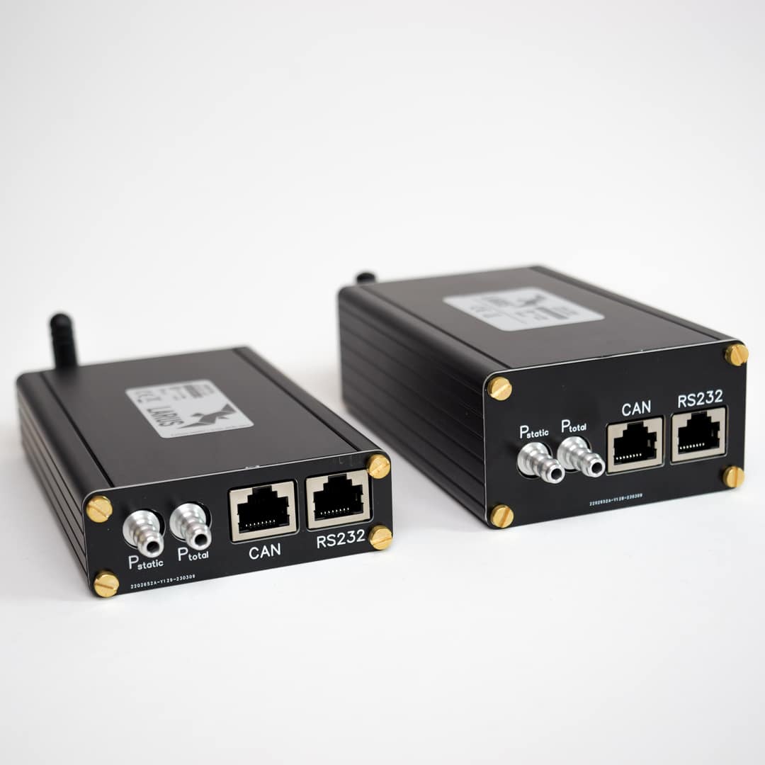
Interfaces: RS232 (x2) - RJ45 / CAN (x1) - RJ45 / Bluetooth - SMA reverse polarity / GNSS-Antenna - SMA normal polarity / microSD
Hose Connector Diameter: 6 mm
Operating Temperature: -30°C to +60°C
Abmessungen Gehäuse LARUS: 145 mm x 79 mm x 28 mm (incl. antenna connectors and hose connectors)
Weight LARUS Essential: 300 g (incl. GNSS antenna)
Weight LARUS Dual-GNSS: 630 g (incl. 2 GNSS antennas)
Material: black anodized aluminum housing
Cable length GNSS antennas: LARUS Essential 4 m, LARUS Dual-GNSS standardmäßig 5 m
Related products
-
Upgrade from LARUS Essential to Dual-GNSS
790,16 €incl. 19% VAT
plus shipping
Delivery time: 5-7 Werktage / Business Days
-
Sale!
LARUS Standalone: Kit consisting of Sensor Box / Vario Display(s)
1.668,53 € – 2.887,84 €incl. VAT
plus shipping
Delivery time: 5-7 Werktage / Business Days
-
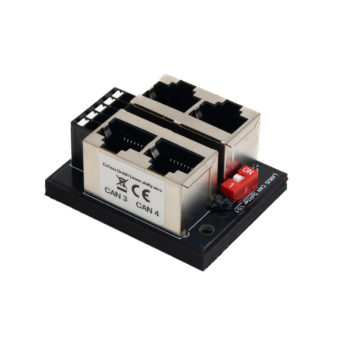
CAN Splitter
35,70 €incl. 19% VAT
plus shipping
Delivery time: 5-7 Werktage / Business Days
-

LARUS Vario Display 57 mm
440,30 €incl. 19% VAT
plus shipping
Delivery time: 3-5 Werktage / Business Days